
Why a C-Frame Machine Fits Power Plug Molding with Removable Blocks
See how removable mold blocks, external insert loading and cable clearance influence C-frame machine selection for power plug and cord connector molding.
2026-09-11 | 9 min read | Category: Application Notes
A power plug molding project involves handling the cable assembly as well as filling the mold. Before each shot, the terminal assemblies must be positioned, the cables routed, and the tooling prepared for closing. When several assemblies are loaded individually, this preparation can occupy a substantial part of the work sequence.
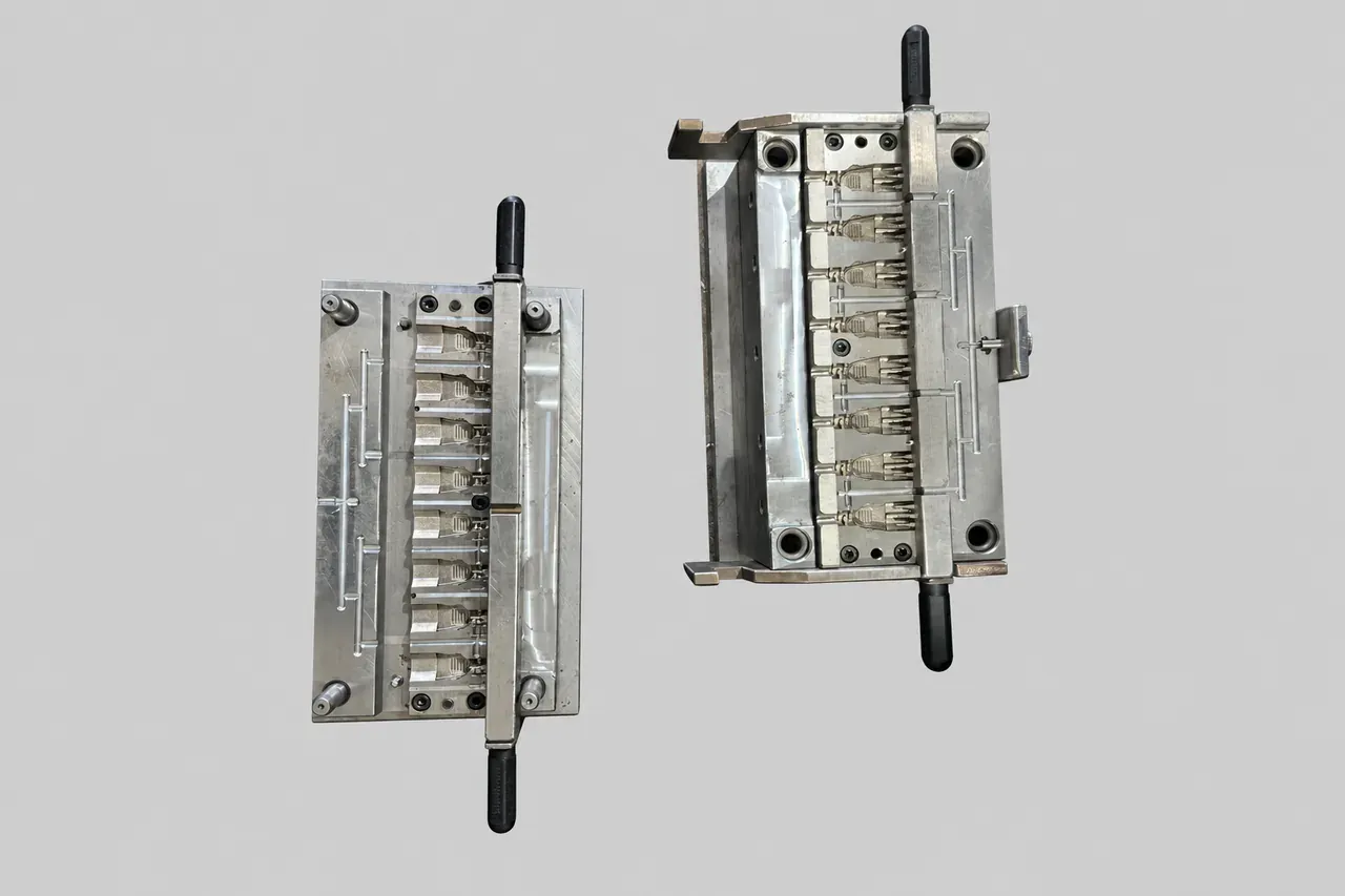
One approach uses two interchangeable, removable mold blocks. One block holds the assemblies being molded while the operator prepares the other outside the mold. A C-frame machine with an open clamping area can accommodate the block, its handles and the attached cables during exchange.
The production footage and tooling photographs accompanying this article illustrate this relationship between mold design and machine access. The key selection question is how the complete cable assembly moves through the workcell.
Move insert preparation outside the mold
In the arrangement described in Deboge’s engineering notes, part of the mold is removable and two matching blocks are prepared for alternating use. Here, “removable block” means the insert-holding part of the mold that is taken out and exchanged during production.
The main mold remains on the fixed platen. The removable block carries the plug or connector inserts and their attached cables. After molding, the block and molded components are removed together, and a block already loaded with the next set of assemblies is placed into the mold.
| Stage | Block A | Block B |
|---|---|---|
| Molding with A | Inside the closed mold | Outside the mold for unloading and preparation |
| Exchange after opening | Removed with the molded components | Loaded block placed into the mold |
| Molding with B | Outside the mold for unloading and preparation | Inside the closed mold |
This arrangement allows some external preparation to overlap with molding. The opportunity depends on how long unloading, insert placement, cable arrangement and block exchange actually take. Opening and exchanging the blocks still require time, so the complete work sequence should be measured when assessing output.
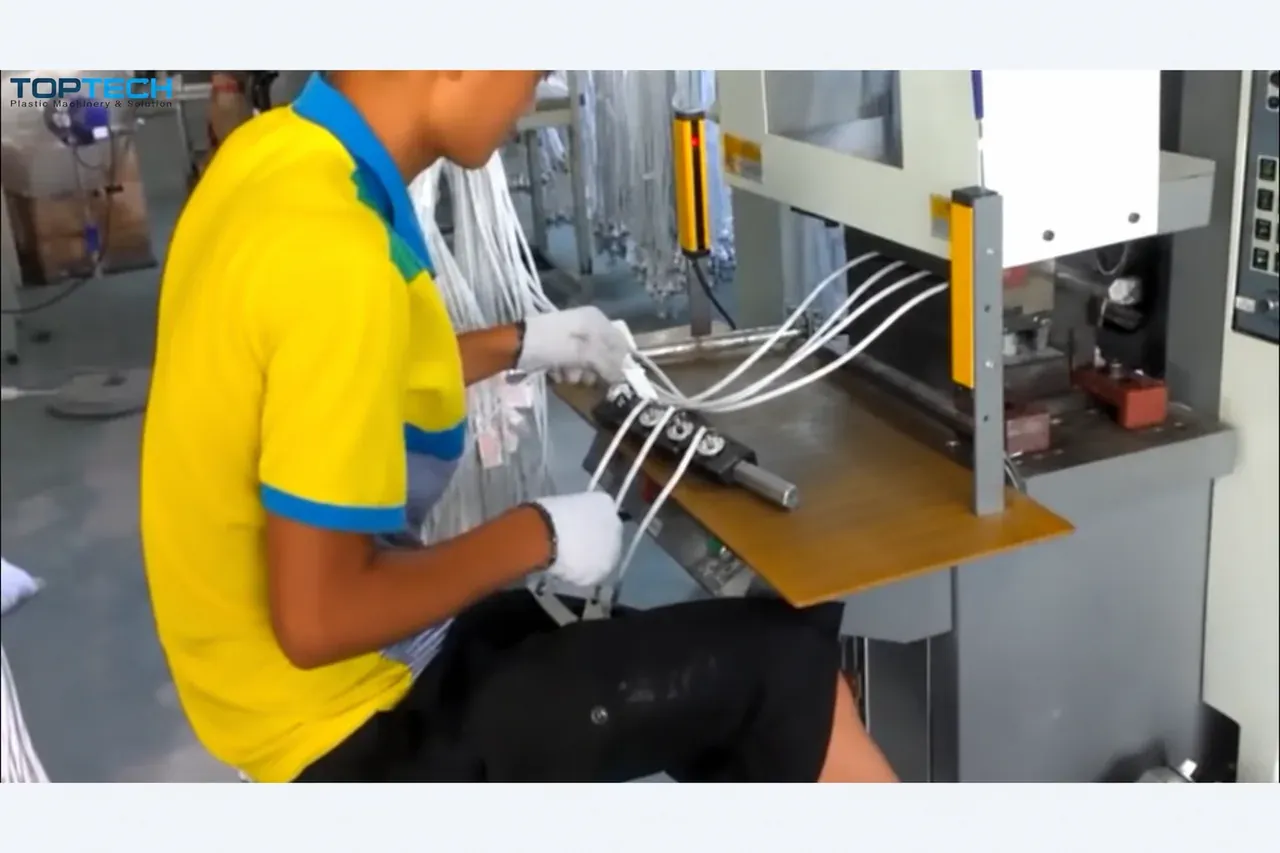
The TOPTECH name shown in these videos is a sub-brand of DEBOGE.
Check the handles and cable path when choosing the frame
The tooling photographs show why mold dimensions alone are an incomplete description of the space required. Handles project beyond the block, an operator must grip them, and the cables move with the assembly.
On a conventional machine with tie-bars around the working area, those elements need to pass through the available opening. Depending on the mold and loading direction, a tie-bar can interfere with the block or its handles. An open C-frame provides access that may suit this exchange path more directly.
For a proposed installation, review the block width including both handles, the required lift and travel path, and the space occupied by the cable bundle. Also establish where the second block and finished assemblies will be placed. These details connect the machine structure to the actual loading task.
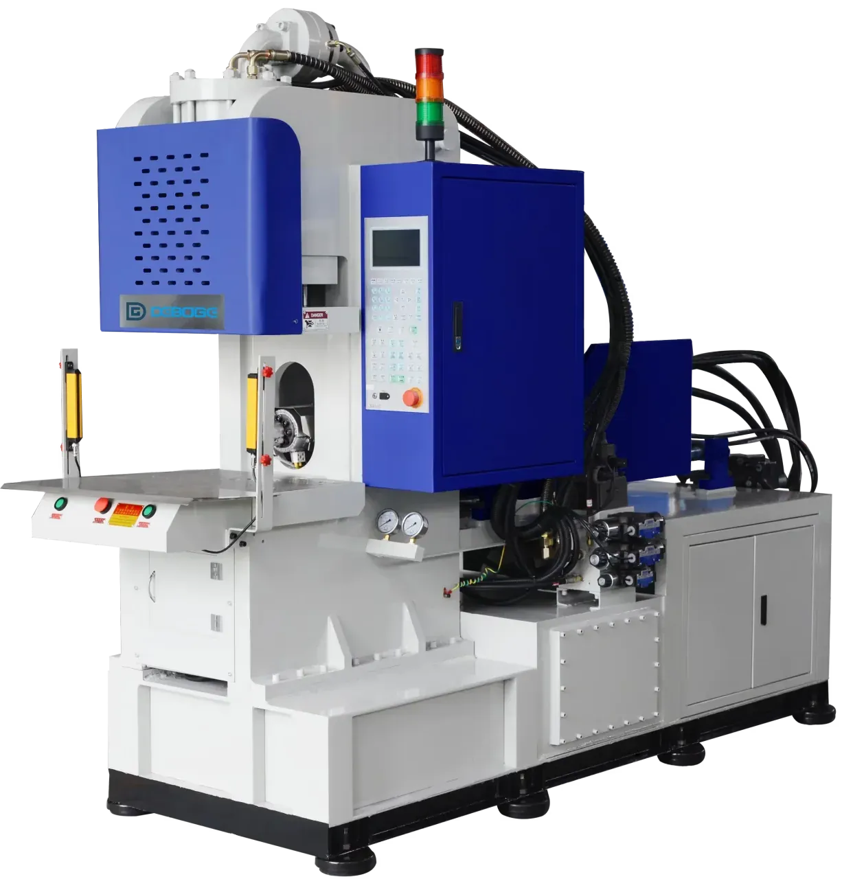
Deboge’s DC Series tie-bar-less vertical clamping machines are defined by their clamping structure. The plug-machine configuration discussed here combines vertical clamping with horizontal injection. Injection direction across the DC Series depends on configuration.
Compare machine and table arrangements
A rotary or slide table can support loading arrangements for many insert-molding applications. For this plug-and-cord workflow, compare what would move, where the loose cables would go, and how insert preparation would be organized.
| Machine or table arrangement | What to evaluate for this application |
|---|---|
| Conventional vertical machine with tie-bars | Whether the loaded block, handles and cables can pass through the available opening without an awkward exchange path |
| Rotary table | How long cables would be supported and managed as the table indexes, including the potential for twisting or entanglement |
| Double slide table | Whether moving two lower mold assemblies offers a useful production benefit for the proposed tool and loading method |
| C-frame with a fixed platen and two removable blocks | Whether alternating the smaller blocks provides the required external loading arrangement while leaving the main mold in place |
In the documented concept, the two removable blocks already provide an alternating preparation arrangement. That gives a reason to evaluate a fixed platen before adding a double slide. Other products, fixtures or automation requirements can lead to a different choice. The broader power plug and cord molding application page provides the application context.
Match cavity count to the mold and injection unit
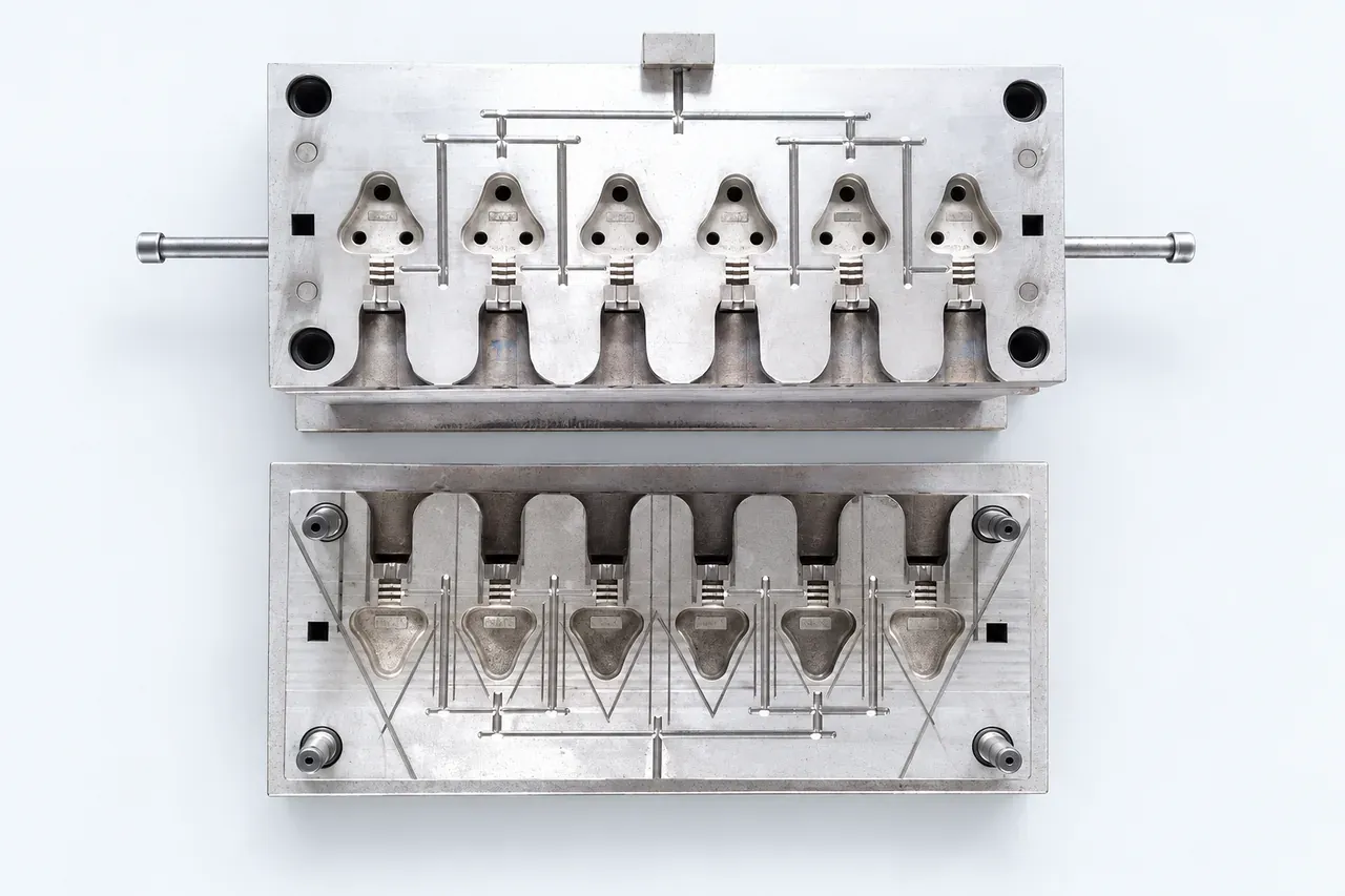
The supplied photographs include six-cavity and eight-cavity mold layouts. These examples demonstrate specific tooling arrangements, rather than a cavity-count rating for every plug machine.
Before choosing a model, review the complete shot, mold fit, required clamp force and block-handling space together. Clamp-force assessment involves projected area and the pressure developed in the mold; geometry and flow conditions also matter. Cavity count alone cannot determine the required machine size. PDI’s process-engineering explanation of clamp tonnage describes these considerations.
The DC-450 and DC-750 parameters confirmed by DEBOGE give the following reference comparison:
| Specification | DC-450 | DC-750 |
|---|---|---|
| Clamping force | 450 kN | 750 kN |
| Screw diameter options | 36 / 40 mm | 40 / 45 mm |
| Theoretical injection volume, corresponding to those screw options | 175 / 220 cm³ | 226 / 286 cm³ |
| Opening stroke | 200 mm | 270 mm |
| Maximum opening distance | 400 mm | 470 mm |
Each injection-volume value belongs to the screw option in the same position. The sheets also list PS reference shot weights; those values must not be treated as the achievable weight of a different resin or as the finished weight of an assembly containing metal and cable.
For an actual project, review the resin, total molded volume including runners, mold dimensions and opening requirements against the selected configuration. Horizontal injection identifies the arrangement of the injection unit; its usable capacity must be checked from the selected unit and process requirements.
Use the actual cable assemblies during mold trials
An archived plug-mold trial report separates the wire samples into three groups. It lists two groups with a 6 mm diameter and a third with a 7.5 mm diameter, and states that three pieces of wire from each group were measured. Later pages contain photographs of molded samples and dimensional measurements.
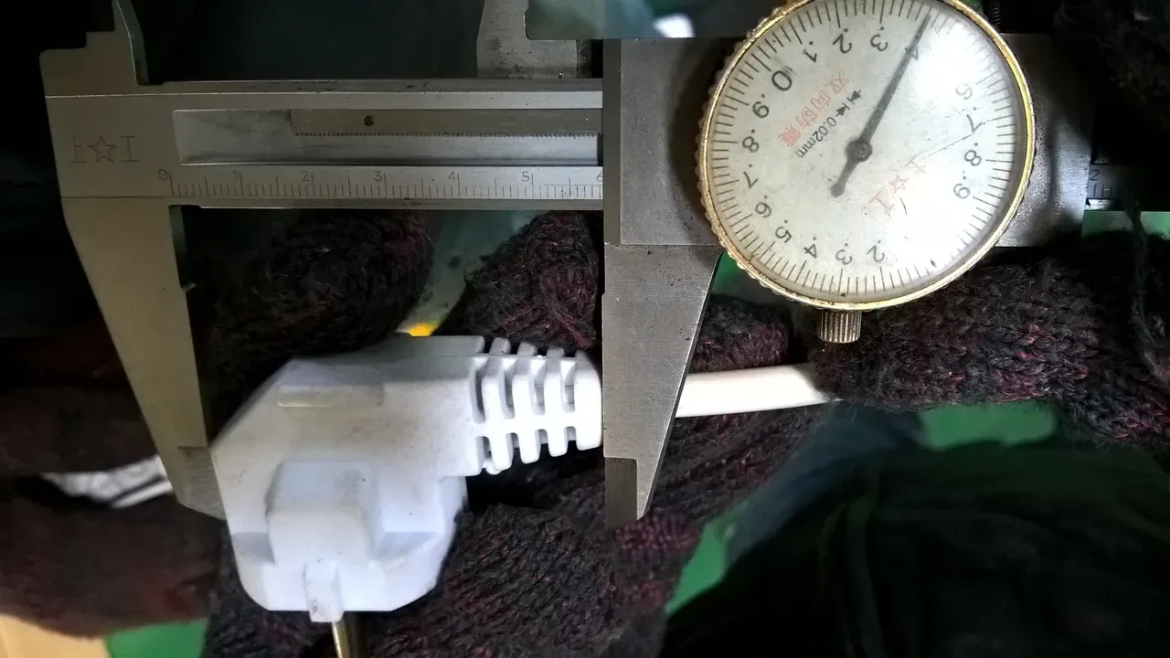
This record provides a useful example of recording actual wire groups separately. It does not explain the construction difference between the two 6 mm groups, so that difference should not be assumed.
For a new trial, identify the cable and terminal assemblies by drawing or sample reference. Check how each assembly fits the block, how the cable passes through the mold boundary, and whether the molded dimensions match the agreed drawing. Review all cavities and both removable blocks rather than relying on one photographed part.
The archive illustrates sample checks. It does not establish the cycle time, yield or electrical qualification of a new production project.
A turnkey production solution tailored to your plug product
DEBOGE can provide a turnkey production solution tailored to the plug the customer needs to produce, the cable and terminal specifications, and the production requirements. The supply scope can include injection molding machines, molds, auxiliary equipment, wire stripping machines, terminal crimping machines and other equipment selected for the project.
Evaluating wire preparation, terminal crimping, insert loading and molding together helps match the equipment to the same product requirements and production target. This brings the upstream preparation equipment, mold and injection molding machine into a coordinated production plan.
To assess a similar workcell, send Deboge the product drawing or photographs, cable dimensions and length, terminal-assembly details, resin information and intended output. If a mold exists, include its dimensions, cavity count, opening requirements, and a view of the removable block with its handles.
A short video of the current loading and exchange method can help explain access constraints that are difficult to capture in a specification table. These inputs help DEBOGE define the equipment combination and process arrangement for the turnkey solution.
Related Reading
Have a question about this topic?
Contact Deboge engineering for technical questions specific to your application and production requirements.