
How a Rotary Table Machine Molds Foamed Bottle Stopper Components
A rotary table carries bottle stopper molds through injection, cooling and release. See the foamed parts and how to check their flanges, openings and weight.
2026-11-10 | 3 min read | Industry: Packaging
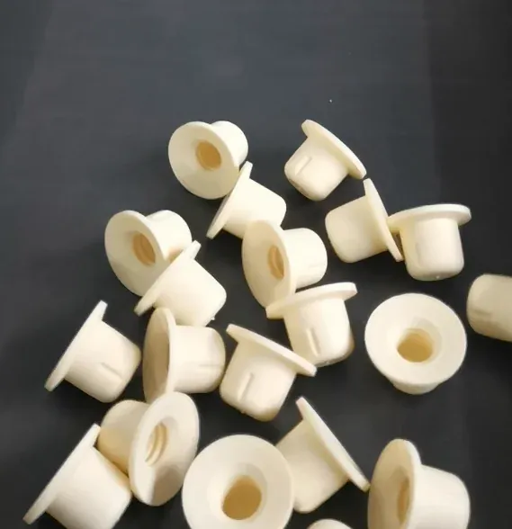
The bottle stopper component in this project has a short cylindrical body, a wide flange and an opening in the center. The customer wanted a light part with a cork-like feel and consistent dimensions across a production batch. DEBOGE used foam injection molding to form the part and a rotary table to carry multiple molds through the cycle.
Why the stopper needs time in the mold
The cavity defines the outside profile while the material expands and takes shape inside it. At release, the foamed body needs to hold its round section and the thin edge of the flange needs to come away cleanly. If that edge bends during removal, a trial should examine both the cooling time and how the part is released.
A rotary table machine lets one mold cool while another is at the injection position. That matters for this part because the time it needs to hold its shape can extend beyond the time it takes to fill the cavity.
Following one mold around the rotary table
The table indexes a mold beneath the vertical clamp. The upper platen closes the mold, and the machine injects the material. The material expands in the cavity and begins to cool. After the clamp releases the tool, the table can advance it to the next position and bring another mold under the platen. The stopper components come out once they can hold their shape during removal.
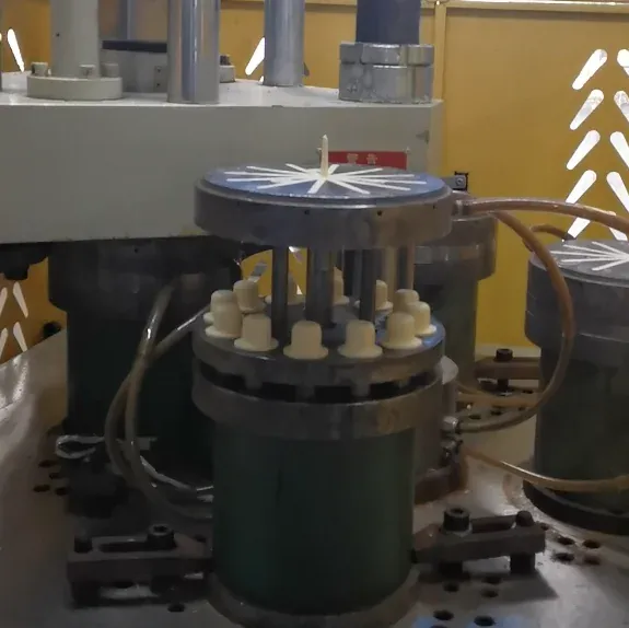
The 36-second DEBOGE production video shows the rotary foam molding setup used for bottle closure components.
What to check on a molding trial
Keep trial samples grouped by mold position and compare them after the same cooling interval. Record the following for each group.
- Body and flange. Measure the body diameter in two directions, then check the flange thickness and profile against the drawing. Inspect its rim for distortion from removal.
- Central opening. Check its size and location relative to the body. Measuring from the opening to the outer wall at several points helps reveal an off-center opening.
- Part weight. Weigh individual samples and record their mold positions. If two parts have similar outside dimensions but different weights, the records give the process team a starting point for checking filling and foam expansion.
For a similar project, send a dimensioned drawing or samples, the proposed material, the target part weight and the required hourly output. These inputs help DEBOGE review the mold layout and the cooling time available on the table. See what to prepare for machine selection or discuss a bottle stopper project with DEBOGE.
Related Reading
Have a similar application?
Contact Deboge engineering to discuss your production requirements and machine configuration.