
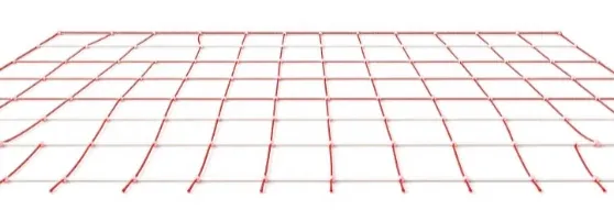
Rope Net Connector Molding with Automated Rope Positioning
See how DEBOGE uses vertical clamping and automated rope positioning to mold connectors at rope net intersections, with tooling and inspection considerations.
2026-11-04 | 5 min read | Industry: Rope net manufacturing
A rope net needs more than a repeatable plastic shape. Each molded connector must form around the intended intersection of flexible ropes, while the surrounding strands remain correctly positioned. If a rope shifts before the mold closes, the connector can form at the wrong point or capture an incorrectly seated strand.
For this DEBOGE project, the molding task is to create plastic connectors directly around rope intersections. The supplied project summary describes a vertical clamping machine combined with automated rope-positioning fixtures. The key engineering task is to coordinate the rope layout, mold location and handling sequence before injection begins.
The product: molded connectors at rope intersections
This is an insert molding application: the ropes are positioned first, and plastic is then molded around the selected junctions. The tooling must define both the connector shape and the paths where the ropes enter and leave the cavity.
The product drawing should establish the intersection spacing, rope arrangement and permitted connector position. These inputs determine how the net is located in the tooling and which sections need support outside the mold.
| Project element | Requirement for molding |
|---|---|
| Product | Plastic connectors formed around rope net intersections |
| Insert handling | Guide and locate flexible ropes before mold closing |
| Tooling | Align each intended junction with its molding cavity |
| Machine arrangement | Vertical clamping integrated with rope-positioning automation |
| Production objective | Repeatable connector placement with less manual positioning |
Locating flexible ropes before the mold closes
Unlike a rigid insert that can seat against a defined stop, a rope can bend, sag or shift as it is handled. A usable loading arrangement must control the position of the crossing strands and support the adjacent lengths without pulling the intersection away from the cavity.
The project summary describes fixtures that guide the rope, maintain tension and hold its position through the molding sequence. Gravity alone is not a locating method for this product. The tooling and holding arrangement must establish the required rope paths before closing; operators should never need to hold a strand in place during closing or injection.
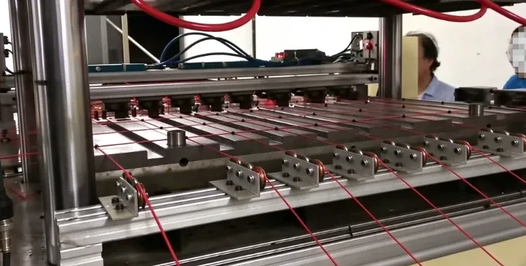
The fixture review should cover the rope’s incoming condition, how the crossing strands are seated, and how the molded net is released. Rope tension is a setup variable to define for the actual material and product geometry; the source does not specify a tension value or a particular feedback-control system.
Vertical clamping and automation integration
Vertical closing provides access to the lower tooling area for locating the rope assembly. In this project, positioning automation supports the insert-handling task, while the mold defines the connector geometry. The handling sequence must be coordinated with machine operation so injection begins only after the insert is correctly located and the mold is closed.
The accompanying DEBOGE video is titled “Fence Injection Molding Automation | Automatic Rope Insert Molding Machine.” The product discussed here is specifically the molded connector at a rope net intersection.
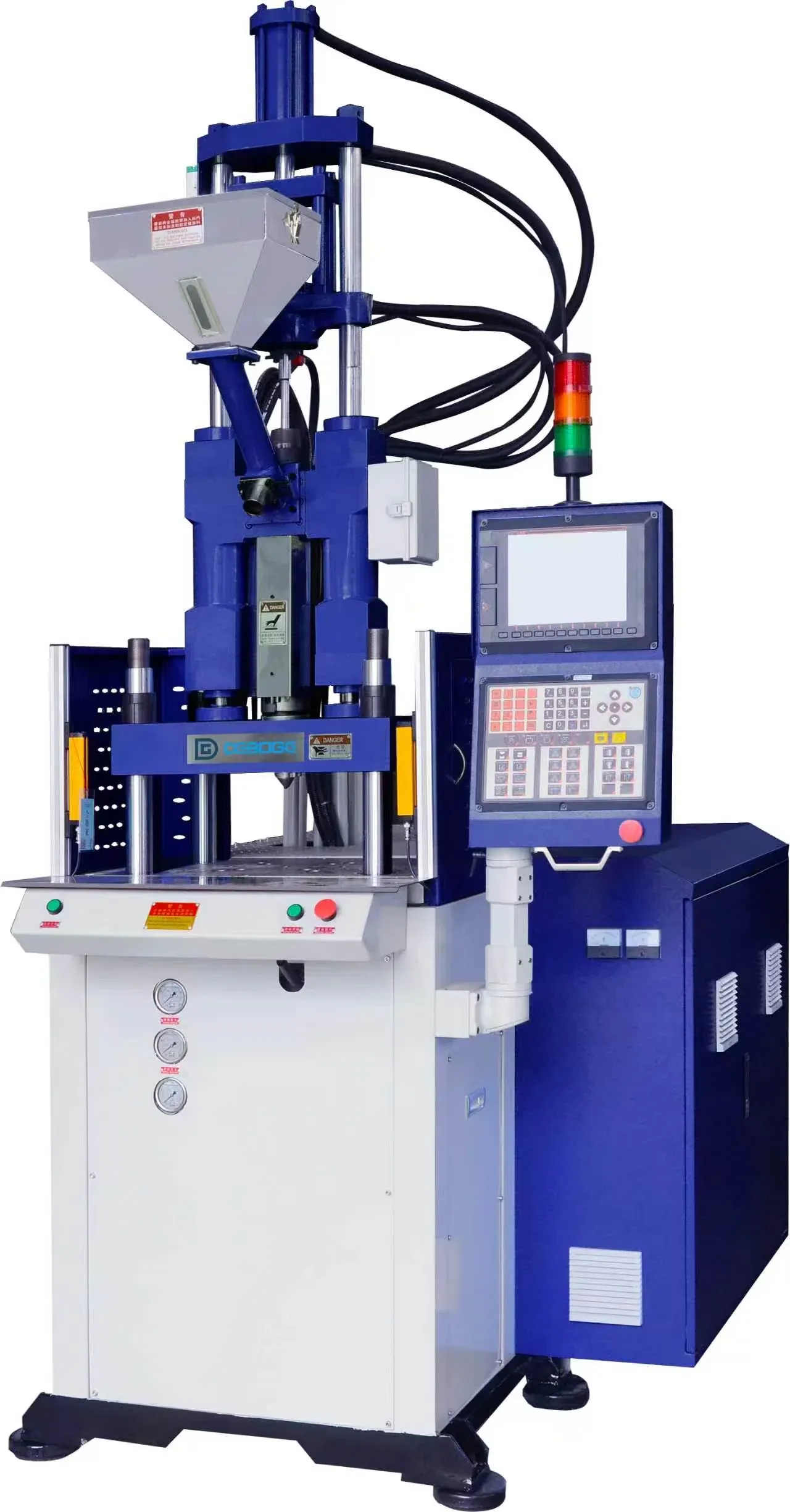
The project brief includes molding at several rope positions as a production requirement. The number of cavities, stations and connectors made per cycle must be established during tooling design. They should be evaluated together with the net dimensions, mold size, injection requirement and handling clearance, rather than selected independently.
Production sequence
- Prepare the ropes. Check the specified rope type, condition and layout before loading.
- Guide and locate the intersections. Position the strands in the fixtures and align the intended junctions with the molding locations.
- Secure the insert and close the mold. Confirm that the rope paths are correctly seated and clear of unintended pinch points.
- Mold the connectors. Inject the specified plastic around the intersections within the defined cavity boundaries.
- Cool, open and release. Allow the connector to set before releasing the molded section from the tooling.
- Inspect the net. Check connector position, molded coverage and the condition of the exposed rope before the next handling stage.
This sequence describes the process requirements. The exact feeding, transfer and removal mechanisms depend on the agreed automation configuration.
What to validate for a new rope net design
The overmolding review starts with the rope and plastic as a combined product. A satisfactory external appearance alone does not establish connector retention or suitability for the intended use.
- Rope and plastic compatibility: specify both materials and check how the rope responds to the molding conditions. Do not assume every rope construction can use the same process.
- Intersection and connector geometry: define the crossing arrangement, molded coverage, connector spacing and allowable position variation.
- Mold entry and exit details: review the boundaries around the ropes for flash, incomplete filling or damage to the strands.
- Handling after molding: establish how the flexible net is supported and released without disturbing newly molded connections.
- Functional acceptance: agree any pull, slip or other product-specific checks, including test conditions and acceptance criteria, before judging production samples.
The supplied project summary reports less manual positioning and more consistent production. These are qualitative observations; it does not provide a measured cycle time, output comparison, defect rate or connector-strength result. For another net design, the requirements and validation should be defined from that product’s intended use.
Frequently asked questions
What is molded in this application?
Plastic connectors are molded directly around crossing ropes. The rope spans between the connectors remain exposed; this is not continuous coating of the entire rope.
Can the same setup make different rope net sizes?
The project allows application-specific mold and fixture design. A different intersection spacing, rope diameter or connector shape requires review of the tooling, handling clearance and molding configuration.
Does vertical clamping hold the ropes in place by itself?
No. Guides, fixtures and the mold’s locating features must constrain the flexible strands. Vertical access helps with the arrangement of insert handling, but does not replace positive positioning.
What information is needed to evaluate a similar project?
Provide a net drawing or sample, rope material and diameter, connector dimensions and plastic specification, intersection spacing, production target and required product tests. DEBOGE can then review the machine, mold, fixtures and automation scope together.
For a similar application, explore custom vertical molding solutions or send your rope net requirements to DEBOGE. The review should establish the product and tooling requirements before fixing the machine configuration.
Related Reading
Have a similar application?
Contact Deboge engineering to discuss your production requirements and machine configuration.