
Metal Insert Molding for Screw Knobs, T-Handle Screwdrivers and Long Nails
Explore DEBOGE metal insert molding examples for screw knobs, T-handle screwdrivers and long nails, with practical guidance on positioning and table selection.
2026-10-23 | 6 min read | Industry: Hardware and hand tools
Molding a plastic screw knob, a T-shaped tool handle and a feature on a long metal nail involves the same basic operation: place a metal insert in a mold, then form plastic around the required area. The practical differences lie in how each insert is located, which surfaces remain exposed, and how the operator loads and removes it.
These three DEBOGE production examples show why an insert molding review starts with the part and tooling. A compact threaded insert needs controlled seating; a screwdriver shaft needs alignment with its handle; an elongated nail needs support and clearance beyond the mold.
Three products, three positioning tasks
| Application | Molding task | Main point to review |
|---|---|---|
| Overmolded screw knob | Form a plastic head around the end of a threaded metal component | Insert seating, exposed thread and knob-to-shaft alignment |
| T-handle screwdriver | Form the handle around the end of the metal shaft | Shaft position, handle geometry and the connection between handle and insert |
| Long nail | Mold the specified feature around an elongated metal insert | Support, loading clearance and the boundary of the molded area |
The examples share a process category, but the mold, insert support and handling arrangement must match each product. The material grade and required functional checks also need to be defined for the individual part.
Plastic screw heads and overmolded screw knobs
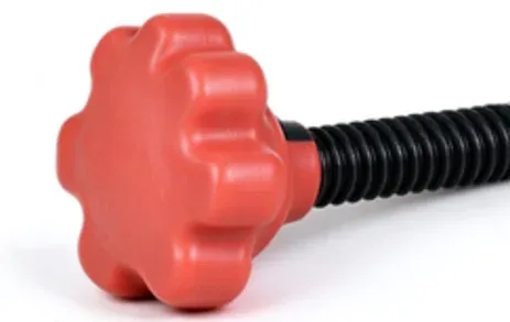
The screw-head sample has a red lobed plastic knob at the end of a threaded metal shaft. The plastic provides an external gripping shape, while the exposed thread retains its fastening function.
The tooling review needs to establish where the insert seats, how much metal is enclosed and where the plastic must stop. Seating variation can change the relationship between the knob and shaft. The drawing should therefore identify the exposed thread length, head position and permitted flash at the molding boundary.
T-handle screwdriver molding
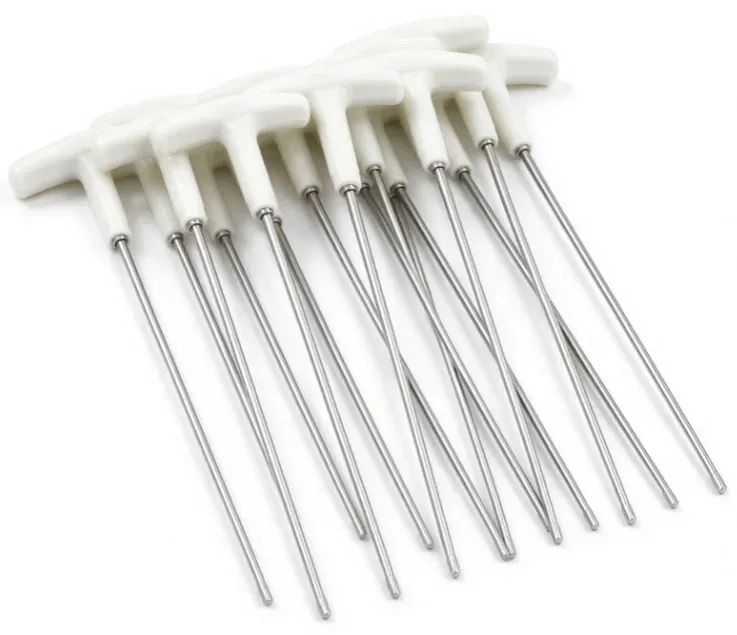
The white T-handle samples illustrate a different interface: the handle surrounds one end of a long metal shaft. The mold must locate that shaft relative to the handle cavity and keep the working length clear of the molded area.
For this application, the review should cover shaft alignment, the specified handle dimensions and how the insert is retained inside the plastic. A clean external surface does not by itself establish connection strength. Any required torque or pull-out check should be defined for the finished tool.
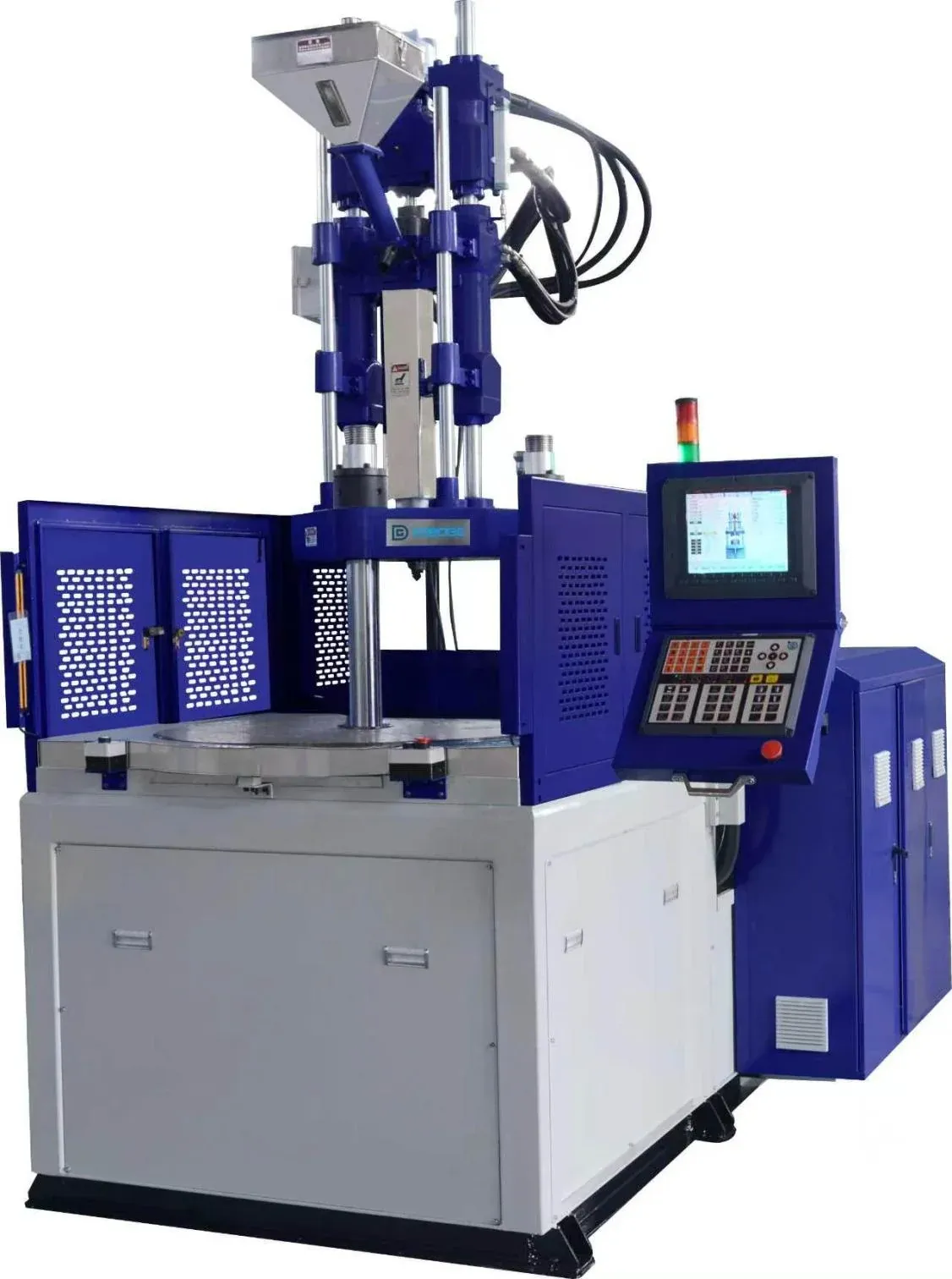
The accompanying T-handle video is identified as a rotary-machine production example. A rotary-table arrangement is relevant when the loading, molding and removal workflow benefits from indexed movement between positions. The actual tool layout and handling sequence determine the configuration.
Long-nail overmolding with a double slide table
The long-nail example uses a double-slide-table vertical injection molding machine. The extended metal inserts make loading space and support outside the molded section particularly relevant.
Before selecting the table arrangement, review how the insert rests in the tool, where its free length extends, and whether it remains clear of the table movement and mold-closing path. The mold must locate the intended overmolding area without relying on an operator to hold the insert during the cycle.
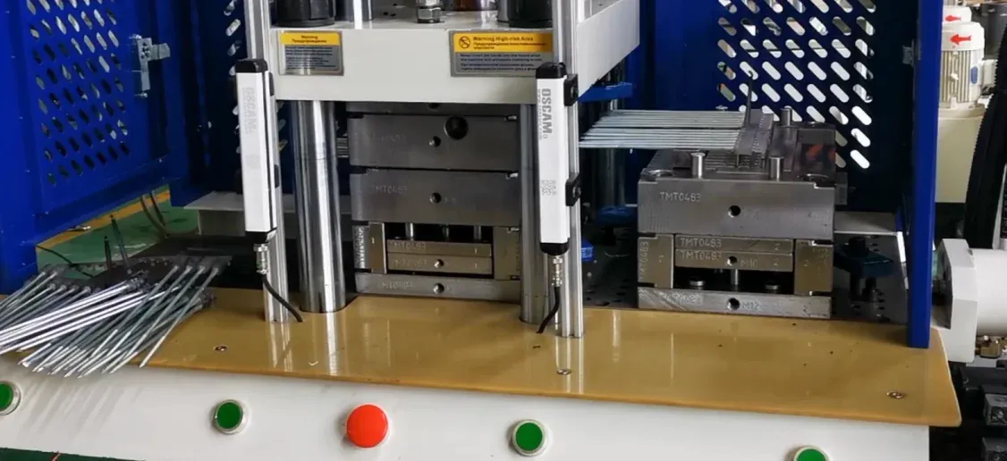
A double slide table supports alternating loading and molding positions. With suitable tooling and guarding, one side can be prepared while the other side is in the molding position. This can reduce waiting associated with insert handling; the achievable output still depends on loading, injection, cooling and removal times.
The shared insert molding sequence
Across these hardware applications, the process described in the project summary follows six stages:
- Prepare the metal insert. Check its geometry, condition and orientation against the part requirements.
- Load and locate it. Seat the insert in the open mold, including any support needed for an extended shaft.
- Move into position and close. Where a moving table is used, transfer the prepared tool into the molding position. The tooling retains the insert through mold closing and injection.
- Inject the specified material. Form the plastic geometry around the area defined by the cavity and insert interface.
- Allow cooling. Keep the part supported until it can be removed without damaging the molded features.
- Remove and inspect. Check insert alignment, exposed surfaces, molded appearance and the specified functional requirements.
Vertical clamping provides access to the open tooling for placement and checking. The fixture and mold design must still prevent the insert from shifting; accessibility alone does not establish molding accuracy.
Selecting the tooling and table arrangement
For a similar metal insert molding application, the useful starting information is a metal insert sample, a finished-part drawing and a clear boundary between the molded and exposed areas. Include the plastic specification, insert surface condition, dimensional requirements and production target.
A fixed platen, single slide, double slide or rotary table is selected around the handling task. Compare the time and access needed to place the insert, check its seating and remove the finished part. An elongated insert also needs adequate clearance throughout table movement, rather than only when the mold is open.
The interface between metal and plastic requires its own review. Insert geometry, surface condition, material choice and molding conditions influence retention. Required torque, pull-out or other functional tests should be agreed for the product; choosing a vertical machine does not establish a particular bond strength.
The supplied project summary reports easier insert placement and more consistent molded appearance across the applications. These are qualitative observations. The practical value of the examples is the connection between part geometry, tooling location and the loading workflow, which should be assessed together before selecting a machine.
Common questions
Can one mold produce all three products?
Each product needs tooling that matches its insert and molded geometry. A machine’s suitability for more than one application depends on the required mold, capacity, access and process configuration.
Does the long-nail example coat the entire shaft?
The supplied example establishes overmolding of a long metal insert. The exact molded area should be defined by the finished-part drawing; the exposed length and support requirements are part of the tooling review.
Does overmolding automatically provide a strong metal-to-plastic bond?
The connection must be evaluated for the actual insert geometry, materials and molding conditions. Functional acceptance checks establish whether the finished part meets its retention requirements.
What determines whether to use a double slide or rotary table?
Compare the mold layout, insert size, loading and removal method, movement clearance and production target. The table arrangement should support the workflow of the specific part.
Discuss your hardware insert molding project
Send DEBOGE the metal insert and finished-part drawings or samples, the specified plastic, the required molded area and the intended production target. These inputs support a review of the mold, insert-location method and vertical molding configuration.
Discuss your tool-handle or hardware insert molding requirements with DEBOGE.
Related Reading
Have a similar application?
Contact Deboge engineering to discuss your production requirements and machine configuration.