
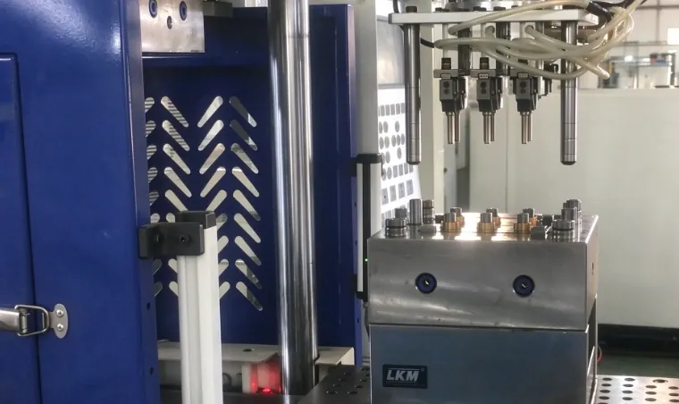
Screw and Nut Insert Molding on a Single-Slide Vertical Machine
Explore DEBOGE single-slide insert molding for screws and nuts, with practical guidance on insert positioning, thread protection, tooling and the loading cycle.
2026-11-04 | 5 min read | Industry: Hardware and fasteners
Plastic-overmolded screws and nuts combine a molded plastic feature with a metal fastening interface. The molding task is to form the specified plastic shape while keeping the insert located and the required threads accessible. A screw with an exposed shaft and a nut with an internal thread therefore need different locating and molding-boundary details.
These two DEBOGE examples use a single-slide vertical injection molding arrangement. The lower tooling slides out for insert placement and part removal, then returns beneath the clamp for molding. This article explains the screw and nut applications and the sequential loading cycle that connects them.
DEBOGE’s descriptions of both production videos identify robotic placement of the metal inserts into the mold. The robot handles the transfer step; the mold’s locating features establish the final insert position. Robotic loading and the single-slide molding sequence must therefore be considered together.
Two fastener interfaces to control
In metal insert molding, the metal part is located in the mold before plastic is injected around the specified area. For threaded hardware, the drawing needs to distinguish the molded region from the surfaces that must remain available for fastening.
| Application | Insert-location task | Functional area to preserve |
|---|---|---|
| Screw insert molding | Locate the screw relative to the molded feature and control shaft alignment | The specified exposed shaft and external thread |
| Nut insert molding | Seat the nut or threaded insert at the required position and depth | Internal-thread access and the required mating opening |
The comparison identifies the tooling questions, not a common mold for both products. Each screw or nut geometry needs its own cavity, locating features and acceptance criteria.
Screw insert molding: alignment and exposed thread
The screw application forms plastic around a selected part of a metal fastener. The mold must locate the insert so the molded feature sits in the intended relationship to the screw axis, while the required shaft length remains outside the plastic.
Tooling review should start with insert seating, exposed thread length and the boundary of the molded area. A screw that is not fully seated can shift the plastic feature along the shaft or change its alignment. The loading position should therefore make it practical to check the insert before the slide returns to the clamping area.
The screw video’s description identifies a robot transferring screws into the mold before injection. For additional product examples, see the screw knob, T-handle and long-insert case study.
Nut insert molding: location and thread access
For the nut application, the plastic forms around the outside of the metal insert while the required internal thread remains usable. The mold design must establish the insert’s position, seating depth and relationship to the finished plastic part.
The thread-protection approach depends on the actual nut geometry and mold design. The review should define how the opening is protected from unwanted plastic and how the part is released without damaging the insert or molded feature. A clean-looking outer surface does not establish that the internal thread is usable; the required thread check belongs in the inspection plan.
Retention within the plastic is a separate requirement from thread function. Any resistance-to-rotation or pull-out requirement should be defined and tested for the intended product, considering the insert geometry, plastic and molding conditions together.
The nut video’s description likewise identifies robotic transfer into the mold. The gripper and locating features need to accommodate the actual nut geometry and release the insert without disturbing its seated position.
How the single-slide cycle works
A single-slide table brings the lower tooling out to an accessible loading position. This makes insert seating and part removal easier to organize around one work position. The insert still needs positive location in the tooling; gravity may assist seating, but does not prevent every movement during closing or injection.
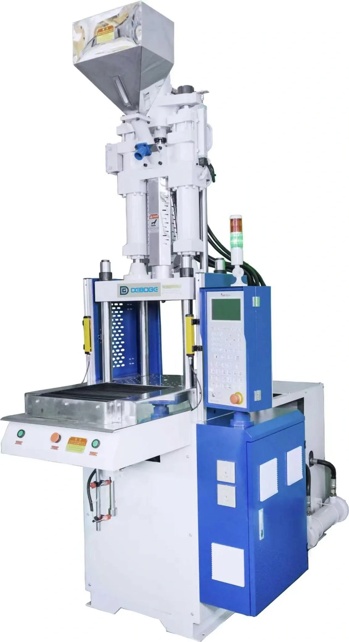
The workflow is sequential: load, slide in, mold, slide out, unload. Loading the next inserts on the same lower mold takes place after the molding cycle, once the tooling has returned to its loading position.
For a robotic loading arrangement, the layout review must include access to the inserts, the placement path and clearance for slide movement and mold closing. Insert supply, finished-part removal and the checks required before closing are separate parts of the automation scope; they should be specified rather than inferred from robotic placement alone.
- Load and inspect the inserts. With the slide at its loading position, place each screw or nut in its locating feature and check seating and orientation.
- Return the slide. Move the lower tooling into the molding position through the machine’s operating sequence, with hands clear of the moving tooling.
- Close and inject. Close the mold vertically, then inject the specified plastic around the defined insert area.
- Cool and open. Allow the molded feature to set before opening the mold.
- Slide out and remove. Return the tooling to the loading position, remove the molded parts and check the mold before reloading.
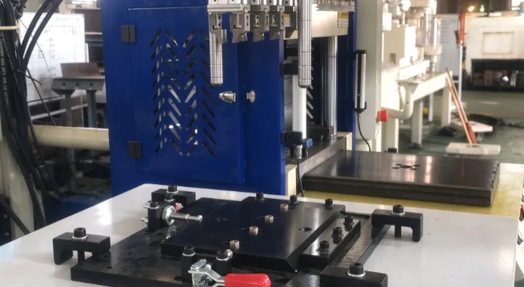
If a production target requires loading to overlap with molding, a double-slide arrangement or another separate-station configuration needs its own review. That is a different workflow from the single-slide examples here.
Tooling and inspection inputs for a similar project
Machine selection should follow the part and mold requirements. The project summary describes more convenient loading and more organized handling; it does not provide measured output, cycle-time savings or a defect-rate comparison.
For a new screw or nut application, establish:
- Insert definition: dimensions, tolerances, thread specification, seating surfaces and the condition of supplied metal parts.
- Molded feature: plastic geometry, permitted coverage, exposed interfaces and acceptable flash at the metal-to-plastic boundary.
- Material and retention requirements: the specified plastic grade, insert preparation and any mechanical retention features, followed by product-specific validation.
- Mold and machine fit: mold dimensions, opening and removal clearance, required injection capacity and the loading method.
- Acceptance checks: insert presence and position, complete filling, thread usability, dimensional checks and any required torque or pull-out tests.
These inputs allow the machine configuration and inspection plan to be assessed for the actual part, rather than inferred from the screw or nut category alone.
Frequently asked questions
Can one machine concept support both screws and nuts?
Yes, the single-slide concept can be evaluated for both. The actual insert geometry, mold size, injection requirement and loading/removal method determine whether a particular machine configuration is suitable. The two products do not necessarily share the same mold.
Can the same slide be reloaded during injection?
No. In the ordinary single-slide sequence, the lower mold is beneath the clamp during molding. Reloading follows mold opening and the return to the loading position.
What should remain clear of plastic?
The drawing should define the exposed screw thread or shaft and the nut’s required internal-thread opening. Tooling must control the molding boundaries, and finished-part inspection must check the required fastening interfaces.
What should be sent for a project assessment?
Send the finished-part drawing or sample, screw or nut specification, plastic grade, molded and exposed regions, production target and required functional tests. Include an existing mold drawing if the machine must work with an available tool.
Explore custom vertical molding solutions or send your screw and nut molding requirements to DEBOGE to review the machine, mold and handling arrangement together.
Related Reading
Have a similar application?
Contact Deboge engineering to discuss your production requirements and machine configuration.